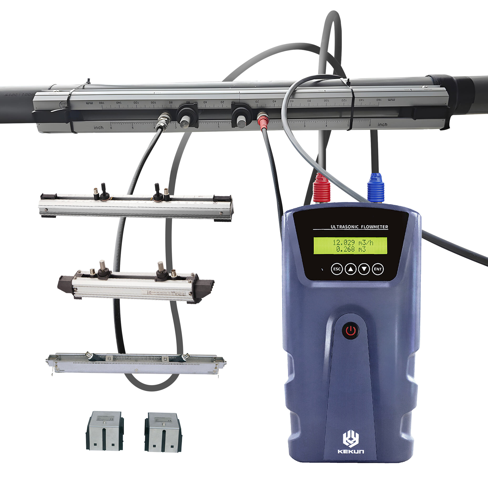
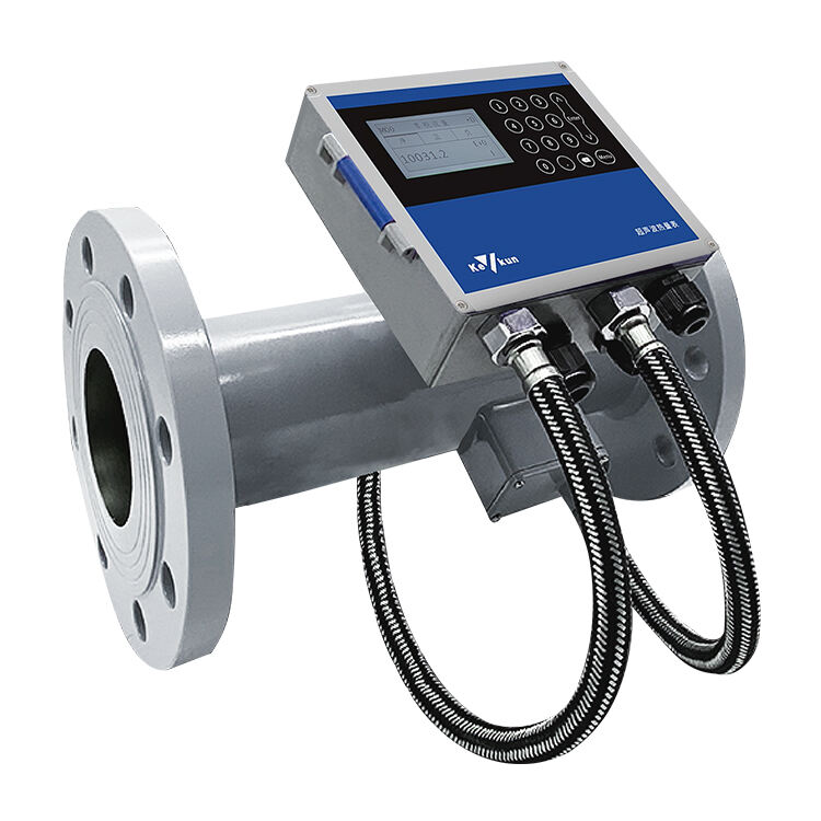
Doppler ultrasonic flowmeter is a device that uses the principle of Doppler frequency shift to measure liquid flow velocity. Therefore, Doppler ultrasonic flow meters are suitable for measuring fluids containing solid particles or bubbles, but not for measuring pure water.

We are currently working on a Doppler ultrasonic flow meter and writing down the process here to keep in mind the obstacles:
Firstly, an ultrasonic flowmeter requires two ultrasonic probes, one for transmitting signals and the other for receiving signals. Therefore, the circuit is divided into two parts: one is used for transmitting the driving signal of the probe, and the other is used for processing the received signal;
Firstly, there is the driving circuit: first, a crystal oscillator is used to generate a square wave signal, and then the square wave signal is used to build a phase shifter using an operational amplifier circuit. Then, the two signals are amplified through the operational amplifier circuit as the driving signal to drive the probe. The final debugged driving signal is shown in the following figure:
The point to note here is that the amplitude and peak to peak value of the driving signal cannot be too small, and it is generally recommended to be greater than 5V.
The above part is divided into three circuits in total. One is the phase shifting circuit built by the operational amplifier, the other is the follower to improve the load capacity, and the last one is the signal amplification circuit. By driving the probe with the above signal, it can be successfully driven.
The second part is the processing part of the received signal, similar to the processing of detector signals. Firstly, the signal is isolated to ensure that the backend signal does not affect the front detector signal. After isolation, the signal is sent to a bandpass filter. The center frequency and quality factor of the bandpass filter should be designed by oneself, and the center frequency should be set according to the parameters of the probe. The center frequency varies depending on the probe.

The output signal of the bandpass filter is sent to the signal amplifier, and the amplification factor is generally set according to actual needs, which is also related to the power supply voltage of the operational amplifier. The amplified signal cannot reach saturation, which will affect the final test results; Then, a bias voltage is added because the detector signal has positive and negative signals, which belong to AC signals. Therefore, a bias voltage is applied and the signal is then sent to the multiplier. The reference signal of the multiplier uses the crystal oscillator output signal mentioned above for differential frequency processing. The final output signal of the multiplier is sent to the low-pass filter. The cutoff frequency of the low-pass filter depends on actual needs. The output signal of the low-pass filter is sent to the 555 timer, which is converted into a pulse signal. The pulse signal is sent to the microcontroller for processing. Using the input capture function of the microcontroller, the recognition result of the microcontroller is calibrated with the actual flow value, and a series of conversion operations are carried out to obtain the desired flow value. In the later stage, a 4-20mA current can be added. Output, more suitable for long-distance transmission. The following diagram shows the driving circuit and amplification circuit, respectively.
Copyright © Weibao Information Technology (Shanghai) Co,Ltd. All Rights Reserved